[Novinky] [Pravidlá] [Roboti] [Poradňa] [Archív]
The mobile robot is built on the three-wheel chassis. Two front wheels serve only as a support and the third is used both for driving and steering. For this purpose are used stepper motors. On the footing is mounted movable arm, which is used as a carrier for necessary sensor equipment. Main mechanical parts of the mobile robot are depicted in Figure 1. In this figure is as S marked point of the rotation of the robot and as B the vertical centre line of the back wheel. The proportions of the robot are listed in Table 1.
Figure 1. Main Parts of the Mobile Robot.
Table 1. Mechanical Parameters of the Mobile Robot.
We used only one sensor for line detection and one for distance from obstacles measurement. Both sensors employ IR diodes or phototransistors. Whereas the sensor for line detection is made as the transmitter and receiver in one package, the sensor for distance measurement is formed from two separate optoelements. The placement of the sensors on the arm is shown in Figure 2 and two views on the robot are in Figure 3.
Figure 2. Movable Arm with the Sensors.
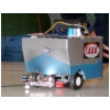
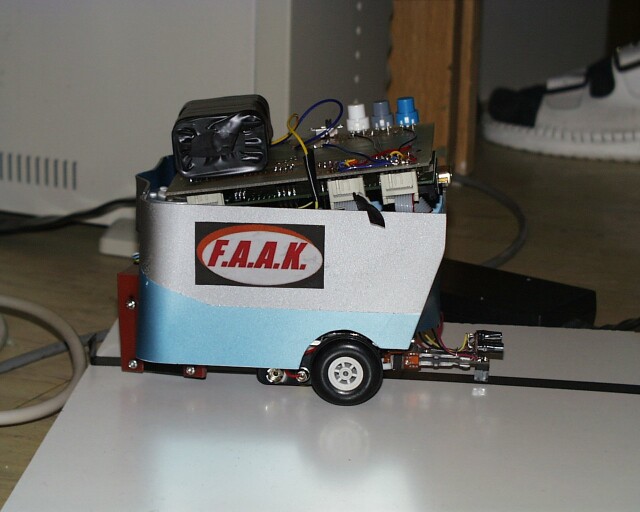
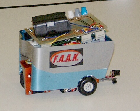
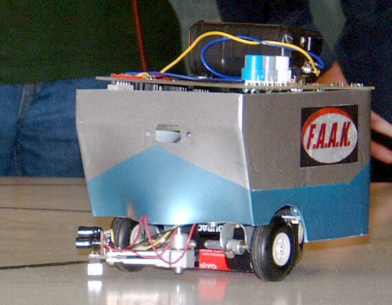
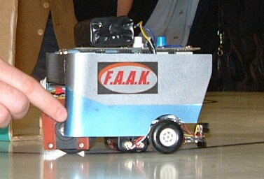
Figure 3. General Construction of the Robot.
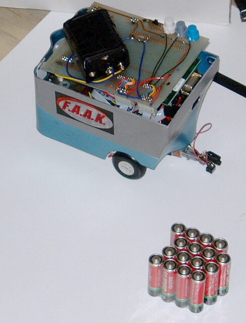
The electronics consists of a control part, drives, sensors and power part. The Digital Signal Processor Starter Kit (DSK) for the TMS320F243 (F243 DSK) treats the control of the mobile robot. The drives consists of three stepper motors. The first is for the arm movement, the second for the steering and the third for the forward and backward movement. As mentioned above, the mobile robot uses IR sensors. One is used for the black line presence measuring (reflective optosensor with transistor output CNY70) and the second for the distance measuring (IR LED LD274, IR phototransistor). The power part contains 12 V accumulator battery and voltage regulators L7805CV (control part), L7808 (operational amplifier LM324) and two LM317T (stepper motor for the arm and stepper motor for the forward/backward wheel).
The mobile robot uses digital and analog interface. Ten digital outputs are used to control up to four stepper motors (two bipolar and two unipolar). Two signals are for each motor (direction, step), one for initialisation and one for enabling bipolar motor bridges. Next two digital outputs are used to switch the infrared LEDs on/off to save energy. Three buttons (start, stop, multifunction) use three digital inputs. The black line presence information utilizes a one digital input. Finally the distance measurement uses a one analog input. The positioning of the DSK in the mobile robot is shown in Figure 4.
Figure 4. TMS320F243 Starter Kit in the Mobile Robot.
The mobile robot uses two unipolar stepper motors (7.5 deg / step). The first UNI1 is for the arm and the second UNI2 for the direction changing. One bipolar stepper motor (0.9 deg / step) drives the wheel forward and backward. <>P The unipolar motor windings are driven by Darlington transistor array ULN2803A. This device contains of eight NPN Darlington pairs that feature high-voltage outputs with common-cathode clamp diodes for switching inductive loads. The bipolar motor windings are driven by push-pull four channel driver with diodes L293D. It is a monolithic integrated high voltage, high current four channel driver designed to accept standard DTL or TTL logic levels and drive inductive loads and switching power transistors. Internal clamp diodes are included.
The control part generates direction and step signals, plus one signal for the enabling L293D bridges and one signal for the loading shift register, which than generates signals for motor windings drivers. As a shift register is used 4 bit PIPO shift register M74HCT194. It features parallel inputs, parallel outputs, right shift and left shift serial inputs, clear line.
The black line presence sensor uses reflective optosensor with transistor output CNY70. The CNY70 has a compact construction where the emitting light source and the detector are arranged in the same direction to sense the presence of an object by using the reflective IR beam from the object. The operating wavelength is 950 nm. The detector consists of a phototransistor (Figure 5).
Figure 5. Optosensor CNY70.
The designed forward current through the emitting LED is approx. 30 mA. Voltage signal from output transistor goes through voltage follower (LM324), then the signal is biased, amplified (3 times), finally signal goes through threshold and voltage follower (also LM324). This TTL output goes to control part. The sensor works properly up to 10 mm from the desktop. The distance measurement works similarly. Instead of reflective optosensor is used infrared emitter LD 274 with extremely narrow half angle 10 deg. The forward current is designed to approx. 50 mA. Phototransistor IRE5 is used as a receiver. Voltage signal from this receiver goes through voltage follower (LM324). This analog signal then goes directly to F243 DSK to A/D converter. This sensor works properly up to half meter from the wall or obstacle.
![]()
 |
 |
 |
 |
 |
 |
 |
 |
[Novinky] [Pravidlá] [Roboti] [Poradňa] [Archív]
© 2002 Richard Balogh
Posledná zmena: 19. septembra 2001.