The tower contains three parts: power supply, transmitter and receiver.
Let's study the transmitter first:
It consists of oscilator, which is turned on and off using the signal TxD (pin 3 on Cannon DB-9 connector of the PC). The cabel to the RCX Infra tower is crossed, so the signal arrives at pin 2.
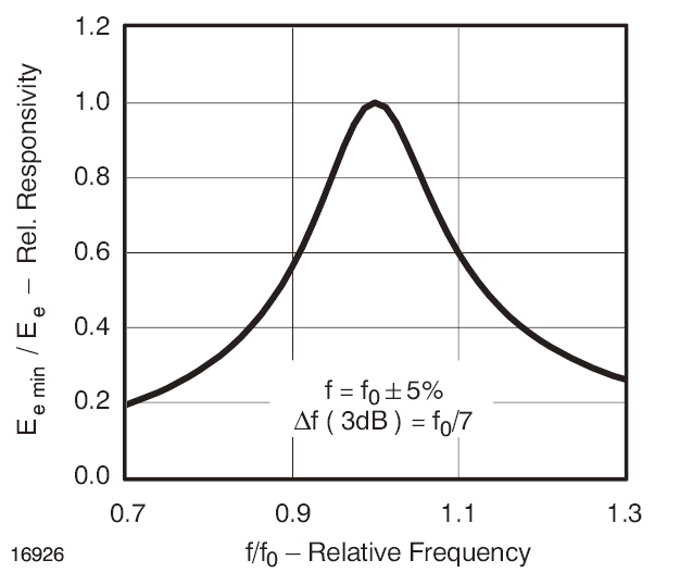
For the receiver, the circuit TSOP 1138 is used. So the frequency of the receiver is 38 kHz. However, as we can see from the frequency characteristics shown below, it has a sufficent sensitivity even on 39,2 kHz (the frequency of RoboSapien IR communication).

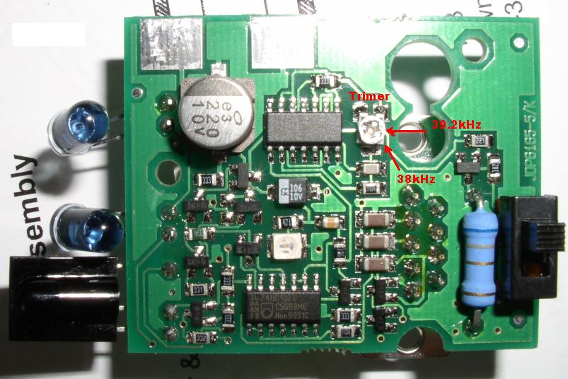
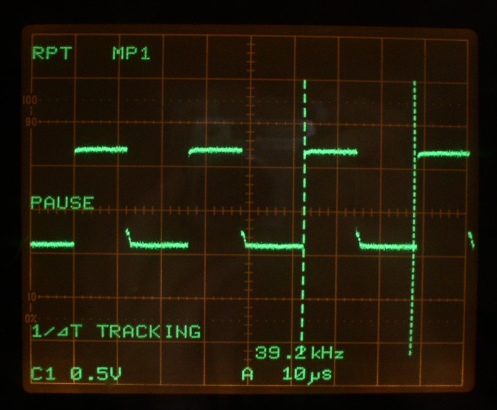
If it would not be suffient, the board contains a trimmer, which can adjust the modulating frequency. Turning by ca. 80 degrees, I could easily change the frequency of the transmitter to 39,2 kHz. It is recommended to use an osciloskope when tuning (and follow the signal on the pin 11). Note that the contact pads for power supply shown on the picture have to be connected somehow to the power source when tuning.


Power supply: in order to save the power, the tower is not on all the time. It is turned on automatically when any transmitting activity occurs. The activity is indicated by a green LED. As a consequence, the oscilator has a relatively slow start, so it is recommended to send at least three idle bits, to make the 38kHz signal stable without problems.
It is necessary to use extended features. A simple application in C++Builder is available Here.
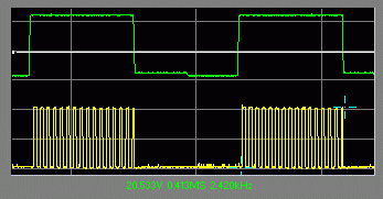
By manually changing the TxD signal (gren) using this program, I could measure the following modulated output at the IR LED (yellow):

© 2005 Richard Balogh and authors.